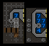
This did, however, lead me to the following (highly theoretical) design:
Top:    Bottom:
###     ###
#7#+    #7##
#%#+    #77#
+%++    ##7#
+=++    #4##
+=+     ###
 =
= is a waterwheel, % is a pump, # is wall, + is floor, 4 and 7 are water (always on the current level). The pump pumps from the south. The water levels shown are for the running system - the 4/7 in the input tile will probably need to be added by bucket brigade while the pump is running. Note that the waterwheel may or may not run before all 4 units of water are in place.
Assuming that spreading water creates flow in the destination as well as the source (which seems likely), this should keep a 4/7 with flow under the waterwheel pretty much all the time. This also assumes a pump will take up only part of the water in its input tile if its output area is too full (this also seems pretty likely, but I'm less confident).
I tested it... and it doesn't work as drawn due to a flaw... You can't place a water wheel that way to connect it to a pump...
I instead did the following:

I then from the z level above designated a pond over the pump output square and had water dumped in until the bottom was all 7/7 and the pump output was 4/7.
Manually start it, and you're off with 75 extra power to do whatever with. I used manual step for a couple hundred steps, and you never see the water change from the way it is in the image above.
I initially left the water wheel the way you have it in your design, but then to get power to the pump i was using 2 gear assemblies and a 1 square axle and that just seemed like a waste when i could turn the wheel and cut out 2 of those pieces.
Edit: Some people don't like Tilesets, here it is in "code" format:
Top:    Bottom:
+###     ###
+#7#+    #7##
+#%#+    #77#
+G%++    ##7#
===++    #4##
++++     ###
= is a waterwheel, % is a pump, # is wall, + is floor, 4 and 7 are water (always on the current level), G is a gear assembly.
Stolen from the post above for simplicity/consistency

 Author
Topic: A New, Reliable Perpetual Motion Design (Read 6154 times)

